Documentation for the latest CamBam release is available here...
Tool Libraries
Libraries of tools can be maintained in the system tab's Tools folder.
Multiple libraries can be defined. This may be useful to group tools for specific purposes, materials or drawing units.
It may also be convenient to create a master library of all tools, then smaller libraries or 'palettes', customised to
specific jobs, into which tools from the master library can be copied.
Tool libraries can be specified in CamBam drawings in the Machining options or Part objects. Libraries
specified at the Part level will take precedence over any set at the Machining level.
Each machining operation can specify a Tool Number. This number is used to look up information about that particular tool
in the relevant tool library.
 If no tool library is specified in the drawing, the default libraries will be searched for entries of this tool number.
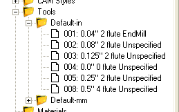
The default libraries are labelled 'Default-in' and 'Default-mm', where the units of the current drawing will be used
to choose the correct library according to the '-in' or '-mm' suffix.
If no tool library is specified in the drawing, the default libraries will be searched for entries of this tool number.
The default libraries are labelled 'Default-in' and 'Default-mm', where the units of the current drawing will be used
to choose the correct library according to the '-in' or '-mm' suffix.
Tool numbers can also be set at the Machining and Part levels.
If a tool number is set at the machining level, this will be the default tool, used by all parts and machining operations,
unless explicitly set in the part or machining operation. The tool selected for the part will override any default
machining tools and will be used for all operations within the part, unless they contain non zero tool numbers.
The tool definitions in the tool library contain information such as tool diameters and profiles, which can be used
in the referring machining operation. If the tool diameter or profile is set explicitly in the machining operation
then this will take precedence over the information from the tool library.
It is possible to use tool numbers without having any matching entries in the tool libraries. In these cases
the tool diameter and profile must be defined in the machining operation.
Managing tools
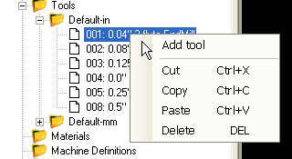
Like the other system libraries, new tools and tool libraries can be create from the context menus presented
when right clicking the system tab's
Tools folder and tool library sub folders.
Tool Properties
Tool libraries and definitions are a relatively new addition to CamBam. Some of the properties available in the tool definitions
are intended for future functionality, but for the current release can be considered for informational use only.
Axial Depth Of Cut
Informational
|
The maximum (Z) depth of cut for this tool.
|
Coating
Informational
|
|
Comment
[New! 0.9.8N]
|
This is a text value that can be included by the post processor when using the {$tool.comment} macro from with the ToolChange post processor section.
|
|
Diameter
|
The diameter of the cutting part of the tool. This will be used to calculate toolpath offsets. For V cutters, this should be set to the diameter
of the cut at typical depths of cut.
|
Flute Length
Informational
|
The length of the cutting part of the tool.
|
Flutes
Informational
|
The number of cutting teeth or flutes.
|
Helix Angle
Informational
|
The helix angle for spiral type cutters.
|
|
Index
|
The tool number that uniquely identifies the tool within the library. The tool index will be used when looking up tool numbers
referenced with the CamBam drawings.
The tool index will also be used within gcode when signalling tool changes etc. This should be set to match
any corresponding tool tables used by the controller which may contain tool height offsets etc.
|
Length
Informational
|
The total length of the tool that typically extends from the collet.
|
Material
Informational
|
Material from which the cutter is made.
|
Max Ramp Angle
Informational
|
The maximum ramp angle. To be used for lead move calculations in future releases.
|
|
Name
|
The descriptive name of the tool which will be used in drop down tool selection lists within the drawing.
The name can be automatically calculated from tool diameter, profile and other parameters
by using the Tool Name Format property of the parent tool library.
|
Notes
Informational
|
Free format text notes relating to the tool.
|
Part Code
Informational
|
A general identifier that may be useful to relate the tool to an external library or tooling catalogue.
|
Radial Depth Of Cut
Informational
|
The maximum 'stepover' to be used by this cutter for crossover cuts.
|
Shank Diameter
Informational
|
The diameter of the non cutting shank of the tool.
|
|
Tool Change
|
The tool change property may contain text that will be used in the post processor when a tool change condition occurs.
The code in this property will be output to the gcode file and will be used in preference to the default tool change
definitions specified in the post processor (for this tool only).
|
|
Tool Profile
|
The shape of the tool profile:
End Mill
Bull Nose
Ball Nose
V-Cutter
Drill
Lathe
|
Tooth Load
Informational
|
Feed per tooth. Intended for use in automatic speed and feed calculations in future releases.
|
Vee Angle
Informational
|
The angle of the V cutter.
|
Tool numbering and naming
Tools can be re-numbered by simply changing their index number in the property grid. If the number entered already exists, the numbers of the following tools will be staggered.
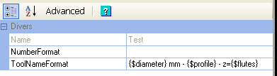 It is also possible to automatically rename using an expression entered into the tool libraries Tool Name Format property.
The expression can contain the following macros:
{$diameter} = Tool diameter
{$profile} = Tool shape / profile
{$flutes} = Number of teeth / flutes
{$index} = Tool number
{$length} = Tool length
{$veeangle} = Tool Vee angle
The tool name will be recalculated whenever the tool properties have changed. It is also possible to rename all the tools if the format expression has changed
by using the Rename all tools from the tool library context menu.
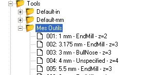
The following image shows the tools renamed using the following format expression.
{$diameter} mm - {$profile} - z={$flutes}